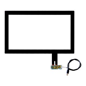
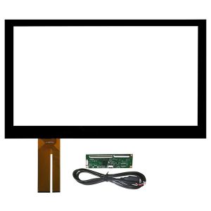
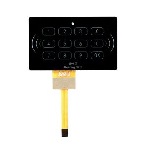
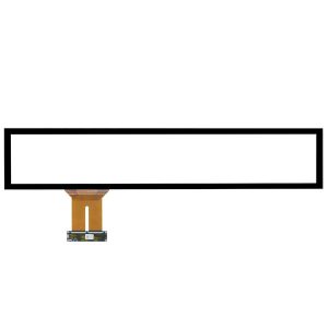
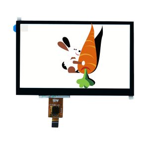
What is a capacitive touch screen?
The way of how capacitive touch screen work is by utilizing the current sensing of human body. The screen is compised of four layers composit glass screen,a layer of ITO was coated on the inner surface and interlayer of the glass screen.
The outermost layer is a thin layer of protective bauxite glass, the ITO coating of interlayer is used as the working surface.There are four electrodes are take out from the four corners. The inner layer of ITO is a shielding layer to ensure a good working environment.
When touching the metal layer with your finger, the coupling capacitor is formed between the user and the surface of the touch screen.This capacitor is a direct conductor to the high frequency current,a tiny current will be sucked from the touch spot by the finger.
This current flows out from the electrodes on the four corners of the touch screen, and the current flowing through the four electrodes is proportional to the distance from the finger to the four corners. The controller computes the position of the touch point by calculating the ratio of the four currents accurately.
How does capacitive touch screen works
Principle overview
To achieve the purpose of multi-touch,the capacitive screens will rely on the electrodes to increase the mutual capacitance.Briefly, the screen will be divided into several blocks. Each set of mutual capacitance modules is working indepently in each area.So the touching situation of each area can be deteced and multi-touch can be simply implemented after processing.
The Working Theory of Capacitive Touch Screen
Capacitive Touch Panel CTP (Capacity Touch Panel) utilizes the current sensing of the human body to work. The screen is compised of four layers composit glass screen,a layer of ITO (nano-indium tin oxide) was coated on the inner surface and interlayer of the glass screen. The outermost layer is only 0.0015mm thick bauxite protective layer, and the interlayer ITO coating.
There are four electrodes are take out from the four corners. The inner layer of ITO is a shielding layer to ensure a good working environment.
When touching the metal layer with your finger, the coupling capacitor is formed between the user and the surface of the touch screen.This capacitor is a direct conductor to the high frequency current,a tiny current will be sucked from the touch spot by the finger.The response speed is less than 0.3 second, and the accuracy can reach to 99%.
Projected capacitive panel
The projected capacitive touch screen etches different ITO conductive line modules on two layers of ITO conductive glass coating. The patterns etched on the two modules are perpendicular to each other and can be regarded as sliders that vary continuously in the X and Y directions.
The X and Y architectures are on different surfaces, a capacitor node is formed at the intersection. One slider can be utilized as a drive line, and the other slider can be used as a detection line.
When a current passes through a wire of the drive line, if there is a signal of a change in capacitance from the outside, it will cause a change in the capacitance node on the other layer of the wire. The change of the detected capacitance value can be measured by the electronic circuit connected thereto, and then converted into a digital signal by the A/D controller, and the computer can perform arithmetic processing to obtain the (X, Y) axis position, thereby achieving the positioning purpose.
During operation, the controller supplies current to the drive line, then forms a specific electric field between the nodes and the wires. The sense line is then scanned column by column to measure the amount of capacitance change between its electrodes, thereby achieving multi-point positioning. When the finger or the touch medium approaches, the controller will immediately detect the alter in the capacitance value between the touch node and the wire, thereby confirming the position of the touch.
When the finger or the touch medium approaches, the controller quickly detects the change in the capacitance value between the touch node and the wire, thereby confirming the position of the touch.
This kind one axis is driven by a set of AC signals, the respense which cross the touch screen will be sensed by the electrodes on other axes.
It is named as “cross-through” induction by the users and also known as projected sending.
There are ITO patterns which is plated with X and Y axis on the sensor.When touching the screen surface with your fingers, the capacitance value under the touch spot will increase according to the distance of the touch spot. The sensor detects the change of the capacitance value countinuously and report it to the processor by computing the touch point with the control chip.
Classification of the Capacitive touch screen
There are two kinds of capacitive touch screen, they are surface capacitive touch screen and projected capacitive touch screen.
Surface capacitive touch screen
A commonly used surface capacitive touch screen features a simple working principle, low cost, and simple circuit design, but it is difficult to implement multi-touch.
Projected capacitive touch screen
The projected capacitive touch screen has the function of multi-finger touch. Both the capacitive touch screens have the advantages of high light transmittance, fast response speed, long life spin, etc. The disadvantage is that as the temperature and humidity change, the capacitance value will change, resulting in poor working stability and frequent drift. You need to proofread the screen frequently, and you can’t wear ordinary gloves for touch positioning.
The projected capacitive screen can be divided into two types: self-capacitive screen and mutual capacitive screen.Take the common mutual capacitive screen as an example, it is composed of a driving electrode and a receiving electrode.
The driving electrode emits a low-voltage high-frequency signal and is projected onto the receiving electrode to form a stable current.
When the human body touches the capacitive screen, the finger and the capacitive screen form an equivalent capacitance due to the grounding of the human body.
The high-frequency signal can flow into the ground through the equivalent capacitance, so that the amount of charge received by the receiving end is reduced. The closer the finger is to the transmitting end, the more obvious the charge reduction, and finally the touch spot is determined according to the current intensity received by the receiving end.
An array of horizontal and vertical electrode is generated on the surface of the glass by the ITO.By comply with the ground,those electrode will form capacitance speratedly which is known as self capacitance. When the finger touches the capacitive screen, the capacitance of the finger will be superimposed on the screen capacitance, which increases the capacitance of the screen.
These lateral and longitudinal electrodes respectively form a capacitance with the ground. This capacitance is known as the self-capacitance, that is, the capacitance of the electrode to the ground. When the finger touches the capacitive screen, the capacitance of the finger will be superimposed on the screen capacitance, which increases the capacitance of the screen.
While touching the detection device, the array of horizontal and vertical electrode will be detected in sequence with the purpose of locating the lateral coordinates and the longitudinal coordinates acoording to the change of the capacitance before and after touched.With combining the resualt,the planar coordinates will be generated.
The way self-capacitance scan is similar to projecting the touch spot on the touch screen to the X-axis and Y-axis direction respectively.The coordinates in the X-axis and Y-axis directions will be computed and finally combined to result the coordinates of the touch spot.
The projections in the X-axis and Y-axis directions are sole for any single touch spot, as well as the combined coordinates. If there are two touch spots which are not in the same X direction or in the same Y direction on the screen,two projections will appear on both the X and Y directions combining four coordinates.But only two of them are real, the other two coordinates are commonly known as “ghost points”. Therefore, the self-capacitive screen can not achieve true multi-touch.
The mutal capacitance screen is also made of ITO to form the lateral electrode and the vertical electrode on the surface on the glass.The difference from the self-capacitance screen is that the capacitors are formed at the intersection of the two sets of electrodes, which the two sets of electrodesconstitute two poles of the capacitor respectively.
When touching the capacitive screen with your finger, the coupling between the two electrodes are effected resulting the change of the capacitance between the two electrodes.The lateral electrodes sequentially emit excitation signals while detecting the mutual capacitance. and all the longitudinal electrodes will receive signals synchronously, so that the capacitance values of all the intersections of the lateral and longitudinal electrodes can be obtained.That is the capacitance of the two-dimensional plane of the entire touch screen.
According to the two-dimensional capacitance change data of the touch screen, the coordinates of each touch point can be calculated. Therefore, even if there are multiple touch points on the screen, the true coordinates of each touch point can be computed.
The advantage of the mutual capacitance screen is that there are fewer wirings, and the difference between the multiple contacts can be recognized and distinguished synchoronously.
Multi contacts can also be sensed by the self-capacitive screen,however, due to that the signal is blur, The self-capacitive screen can also sense multiple contacts, but the blur of the signal it cannot be distinguished.
In addition, the mutual capacitive screen sensing solution also has the advantages of high speed and low power consumption.It can reduce 50% amount of the acquisition cycle because all nodes on one driving line can be measured sychoronously.
This kind of two-electrode structure functions the self-shielding external noise, which improves signal stability at a certain power level.
In any case, the touch position is located by measuring the distribution of the amount of signal change between the X and Y electrodes, which are then processed using a mathematical algorithm to detect the XY coordinates of the touch spot.
Capacitive touch screen structure
The basic structure of the capacitive touch screen is that: the substrate is made of a single layer of plexiglass, and a transparent conductive film is evenly forged on the inner and outer surfaces of the plexiglass, and a narrow cone is formed on the four corners of the transparent conductive film on the outer surface electrode respectively.
When touching the capacitive touch screen with finger, the high frequency signal is turned on at the working surface, and the finger forms a coupling capacitance with the working surface of the touch screen, which is equivalent to the conductor, because the working surface has a high frequency signal, and when touched,a small current is drawn at the touch point. This small current flows out from the electrodes at the four corners of the touch screen. The current flowing through the four electrodes is proportional to the linear distance from the finger to the four corners.
The coordinate value of the contact spot are computed by the controller with the ratio of the four current.This is how the capactive touch screen works.
The capacitive touch screen can be simply viewed as a screen composed of a four-layer composite screen: the outermost layer is a glass protective layer, followed by a conductive layer, the third layer is a non-conductive glass screen, and the innermost fourth layer is also a conductive layer.
The innermost conductive layer is a shielding layer, which shielding the internal electrical signal. The middle conductive layer is a key part of the entire touch screen, and there are direct leads on the four corners or four sides, which are responsible for detecting the position of the touch point.
The uppermost cover layer is tempered glass or polyethylene terephthalate (PET). The advantage of PET is that the touch screen can be made even thinner and cheaper than existing plastic and glass materials. The insulating layer is made of glass (0.4 to 1 mm), organic film (10 to 100 um), a binder, and an air layer. The most important layer is an indium tin oxide (ITO) layer of which the typical thickness of ITO is 50-100 nm, and the sheet resistance is in the range of about 100-300 ohms.
The three-dimensional structure of ITO has a great influence on the capacitive touch screen. It is directly related to the two important capacitive parameters of the touch screen: the sensing capacitor (finger and upper ITO) and the parasitic capacitance (between the upper and lower ITO, the lower ITO and the display screen).
The structure of the capacitive touch screen is mainly to plate a transparent film layer on the glass screen, and then add a protective glass outside the conductor layer above it.With this kind of double glass design,it can protect the conductor layer and the inductor completely, meanwhile access to a higher light transimittance and support the multi-touch better.
Narrow electrodes on all four sides are plated on the capacitive touch screen in order to generate a low voltage alternating electric field in the conductive body.
A coupling capacitor will be generated between the finger and conductive layer under the electric filed of humanbody,when touching the screen. Current generated by the four electrodes will flow to the touch spot.The current intensity is inversely proportional to the distance from the finger to the electrode.Then the controller which is located behind the touch screen will compute the ratior and strength of current to reasulting the exact location of the touch spot.The dual glass of the capacitive touch screen not only protects the conductors and sensors, but also prevents external environmental factors from affecting the touch screen effectively. Even if the screen is stained with dirt, dust or oil, the ability of computing the touch position accurately will not be influced.
Since the capacitance varies with the contact area and the dielectric of the medium, the stability is poor and the drift phenomenon tends to occur. This type of touch screen is suitable for the debugging phase of system development.
Accuracy: 99% accuracy.
Material: completely scratch-resistant glass (Mohs hardness 7H), not apt to be scratched and worn by sharp objects, not affected by common pollution sources, such as water, fire, radiation, static electricity, dust or oil. It also has the eye protection function of goggles.
Sensitivity: less than two ounces of force can be sensed, with a quick response of less than 3ms.
Sharpness: Three surface treatments (Polish, Etch, Industrial) are available. The MTBF of the SMT controller is greater than 572,600 hours (per MILHANDBOOK-217-F1).
Touch life span: Any point can withstand more than 50 million touches, the cursor does not drift after one correction.
The capacitive touch technology is a touch technology that utilizes the change in capacitance generated when a finger is close to a capacitive touch panel.
There are two important capacitance parameters for the capacitive touch,one is the sendign capacitance between the finger and the upper sensing material ( such as ITO ), and the other is between sensing material (such as ITO upper and lower layers) or the parasitic capacitance (such as ITO and LCD). which is between the sensing materials and optical panels.
Parasitic capacitance is generated between the conductor and the conductor, the alter of capacitance will also be generated when the finger conductor approaches the sensing conductor of different voltage.
The capacitive sensing effect is how to detect a small change in the sense capacitance of 0.1 to 2 pF units at a large parasitic capacitance value (30 pico Farad; pF).
Capacitive touch technology is relatively stable and highly reliable. The touch effect will be sensed by the change of capacitance generated on the touch panel, due to that human body is a capacity body.
Christopher Ard, Director of Atmel Marketing pointed out that the sensor design can be single-sided ITO graphics for the lowest functional interfaces, such as single touch points for large virtual buttons, sliders, etc., but the more common implementation is a two-layer design (single The X and Y layers) which more complex performance and precision is required.
Capacitive touch screen data processing
After receiving the touch signal, the touch data will be converted by the capacitive touch screen into an electrical pulse and transmits it to the touch screen control IC for processing.
The signal is first amplified by a low noise amplifier LNA, then converted and demodulated by analog to digital conversion, and finally sent to a DSP for data processing.
There is a M+N (M columns and N rows) physical capacitive touch sensors on the capacitive touch in general.
The M+N interlaced sensors form M*N capacitive sensing points, and the capacitance changes as the user’s finger approaches the touch screen.
The spacing of the sensors (which is the distance between adjacent rows or columns) is typically around a few millimeters, which detects the physical resolution M*N of the touch screen.
The coordinate system between the capacitive touch screen module and the LCD module is completely different.The pixel coordinates of an LCD module are generally dominated by its resolution. For example, a WVGA screen has a resolution of 800*480, which means that there are 800 lines of 480 RGB pixels per line.Thus, a specific position can be located by pixel points (x, y) in the X and Y directions.
The capacitive touch screen module dominates the coordinate system based on the original physical dimensions in the X and Y directions. There must be a reasonable projection method between the two coordinate systems to ensure the correctness of the input and output operations.
Therefore, the DSP processor of the touch screen control IC has to perform pixel mapping conversion between the capacitive touch screen module and the LCD module on the obtained data, thereby ensuring that the touch spot sensed by the touch screen is the spot where the user pointed.
In addition, in order to maintain the stability of the touch coordinates, the touch screen control IC needs to further process the jitter of the touch point, including the jitter of the finger and the noise of the capacitance data.The coordintes will be processed smoothly according to the change of the filter which is altered by the filter coefficient of the low-pass filter.
Finally, before passing the data to the host, every date is analyzed by the software with the purpose to distinguish the function used by each touch.
This process involves determining the size, shape, and location of the area being touched on the screen.
If necessary, the similar touch will be grouped by the processor.The processor will calculate the difference between the start and end points of the user’s touch,if users move their fingers.
The advantages and disadvantes of the capacitive touch screen
Advantages
Only touch no pressure is needed to generate the signal for Capacitive touch screens.
Resistor technology needs routine correction,while only one or no correction after production is needed for capacitive touch screens.
The life span of a capacitor solution can be longer because the components in the capacitive touch screen do not require any movement. In the resistive touch screen, the upper ITO film needs to be thin enough to be elastic so as to be bent downward to contact the underlying ITO film.
In terms of optical loss and system power consumption, capacitor technology is superior to resistor technology.
The choice of capacitor technology or resistance technology depends mainly on the object that touches the screen. For finger touch, a capacitive touch screen is a better choice.
For stylus touch, whether it is plastic or metal, the resistive touch screen can do the job. A capacitive touch screen can also use a stylus, but a special stylus is required to match.
The surface capacitive type can be used for a large-sized touch screen, and the phase is also low, but the gesture recognition cannot be supported at present. The sensing capacitive type is mainly used for small and medium-sized touch screens, and it is adaptable to gesture recognition.
Capacitive technology is resistant to wear and has a long life span, and the maintenance cost is low for users, so it brings the possibility for the manufacturers to further reduce their overall operating cost.
Capacitive touch screens can support multi-touch technology, and unlike resistive touch screens which is slow in reaction,it is not easy to wear.
Disadvantage
The transmittance and clarity of the capacitive touch screen is superior to that of the four-wire resistive screen, and of course it cannot be compared with the surface acoustic wave screen and the five-wire resistive screen.
The capacitive screen is seriously reflective. Moreover, the four-layer composite touch screen of the capacitor technology has uneven light transmittance for each wavelength of light, and there is a problem of color distortion. Due to the reflection of light between layers, image characters are also blurred.
Current: The capacitive screen is used in principle as an electrode of a capacitor component. When a conductor is coupled to a capacitor with a sufficient amount of capacitance between the working surface of the ITO and the interlayer, the current flowing away is sufficient to cause malfunction of the capacitive screen.
Although the capacitance value is inversely proportional to the distance between the poles, it is proportional to the relative area and is also related to the insulation coefficient of the medium.
Therefore, when a large area of the palm or hand-held conductor is close to the capacitive screen instead of touching, it can cause the malfunction of the capacitive screen. This situation is particularly serious in humid weather condition, when holding the display or palms close to the display within 7 cm. or he body close to the display within 15cm,all of those movements can cause malfunction to the capacitive screen.
Another disadvantage of capacitive screens is that they do not respond when touched with a gloved hand or a non-conductive object, because of the addition of a more insulating medium.
Drift: The main disadvantage of the capacitive screen is drift: when the ambient temperature and humidity changed, the environmental electric field will also be changed,causing the drift of the capacitive screen, inaccuracy will be resulted.
For example, a rise in display temperature after power-on can cause drift.When a user touching the screen while the other hand or body side is close to the display it will also drift.
A large object near the capacitive touch screen will drift after being moved, and if there are other people closely around the user while touching, it will also cause drift.
The drift of the capacitive screen is the inherent technical insufficiency. Although the environmental potential surface (including the user’s body) is far away from the capacitive touch screen, it is much larger than the finger area, and they directly affect the measurement of the touch position.
Others: In addition, many linear relationships should be nonlinear theoretically. For example, the total amount of current drawn by people with different body weights or different finger wetness is different.The change of the total current amount and the four partial currents are a nonlinear relationship.
The four-corner custom polar coordinate system used in the capacitive touch screen does not have an origin on the coordinates. After the drift, the controller cannot detect and recover. Moreover, after the four A/Ds are completed, the values of the four divided flows are touched. The calculation process of the X and Y coordinate values of the point on the Cartesian coordinate system is complicated.
Since there is no origin, the drift of the capacitive screen is cumulative which frequent calibration on site is needed.
The outermost bauxite protection glass of the capacitive touch screen is very scratch-resistant, but can not stand any knocking from nail or any hard objetc. The interlay ITO will be affected even there is a small hole on the screen. The capacitive screen will not work properly, whether the interlayer ITO is hurt or the inner surface of the ITO layer is broke during the installation or trnasporation.
FAQs about Capacitive touch screen
- For capacitive touch screen users, the following procedure is highly recommended:
First install the driver for the capacitive touch screen according to the manual,then click the button of “Start”/“Program”/“Microtouch Touchware” to run the screen calibration program.The calibrated data will be saved automatically in the controller’s register.No calibrate is need when you restart the system.
- Calibration operation is mandatory when the display resolution or display mode of the touch screen is changed, or when the cursor does not correspond to the touch point due to thatthe refresh frequency of the touch screen controller is adjusted by itself.
- In order to ensure the normal operation of the touch screen system, you must also remember that do nto install two or more touch screen drivers on one host, which lead to conflicts in the operation system which may prevent the touch screen system from working properly.
- When you found the cursor is not moved or can only be moved in a local area, check whether the touch area of the touch screen is always pressed by other touch objects.For example, once the touch screen is pressed by the display case or the cabinet case, it is equivalent to a certain point being touched, resulting the coordinate position fed back to the controller is not accurate.
- As mentioned earlier in this article, once you found there is inaccurate click and drift while changing he display resolution or adjusting he screen size or installing the system, the relocating applicate within positioning program need to be started.But a thinner pen or fingertip is preferred while positioning,since they are more accurate.
- The surface acoustic wave touch screen demands a high working environment. It must be operated in a clean, dust-free environment, and the dust on the surface of the touch screen should be cleaned regularly. Otherwise, the dust in the air covers the periphery of the touch screen. When the stripe or transducer is reflected, it affects the correct positioning of the system.
- Keep the surface of the touch screen away from water droplets or other soft sticky things otherwise the sound wave screen of the surface it not accurate due to the error of mistaking them as hand touch.
In addition, wipe the stains on the surface of the screen carefully from center to the rear with soft dry cloth or detergent, or industrial alcohol or glass cleaning solution.
- If you found the response is very slow when touch the surface acoustic wave touch screen by hand or other objects, it indicates that the touch screen system is old, the internal clock frequency is too low, or the water droplets on the touch screen surface are moving. To get the touch screen back to a quick response, you must re-replace or upgrade the system, or use a rag to dry the water on the surface of the touch screen.
- The touch screen generally uses the serial port for signal transmission, the signal is taken from the PS/2 port, and the TPS screen is directly powered from the host power supply.If the indicator is off, it shows the signal is not taken and the PS/2 line on the control box may be broken.If the light is on, but does not flash,it means the control box is broken,you need to replace the control box.If it still not work after replacing the control box, it may because the screen is pressed too tightly.Loosen the screws a little bit. It is not easy to damage due to the special material used in the touch screen.The driver will fail to install if the serial port is bad or disabled,because the serial port will be automatically searched when the driver is installed.Even if it can be installed, the mouse will not move or cannot be positioned. It is best not to use the serial mouse to judge the quality of the serial port. It is possible that the serial port 9 is different for each other. If the screen is pressed or the ground wire is not connected, it will result in the inability to locate. If some areas are unclickable or slow to respond, it may be affected by dust, and the outer casing needs to be removed to remove dust.
- When you found there is no reaction after touched, it is very likely that the touch position is inaccurate and the cursor can not be located correctly.Enlarge the distance between the cabinet and the display screen when the cabinet case is pressed against the touch area.Try to loosen the screw of the display case when it is pressed against the touch area.

